
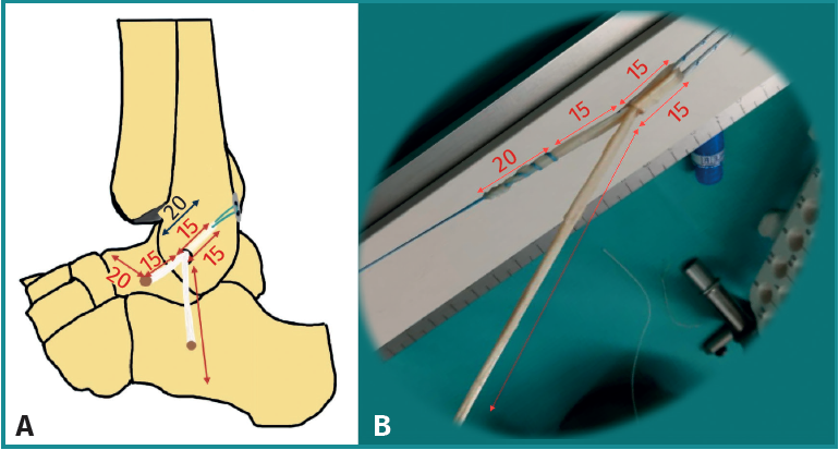
Figure 4. A: referenced drawing of the placement and measurement of the ankle plasty. Note the 15 mm loop in and out of the fibula, the 15 mm to the talus, and the 20 mm of plasty inserted in the talar tunnel. On the other side of the loop, we see the trajectory to the calcaneus and the tunnel; B: image of the preparation of the plasty. Note the 15 mm loop there and back at the calcaneus, the 15 mm trajectory to the talus and 20 mm of the tunnel. Towards the opposite side, the plasty we will use for the trajectory in calcaneofibular reconstruction.